Einführung
Bei mobilen Maschinen – wie landwirtschaftlichen Traktoren, Mähdreschern, Radladern, Baggern und kommerziellen LKW-Kränen – ist die Hydraulikpumpe das Herzstück des Fluidtechniksystems. Die Pumpe wird direkt vom Fahrzeugmotor angetrieben (über Zapfwellen, Steuerzahnräder oder Riemenantriebe) und wandelt mechanische Rotationsenergie in hydraulische Fluidleistung um ($P \cdot Q$) und versorgt Wegeventile, Hydraulikzylinder und Fluidmotoren mit Durchfluss.
Die Auswahl der richtigen Hydraulikpumpenspezifikation für eine mobile Maschinenplattform erfordert das Abwägen mehrerer miteinander verbundener technischer Parameter: erforderliche Systemdurchflussrate ($Q$), Spitzenbetriebsdruck ($P$), Antriebswellendrehzahl der Antriebsmaschine ($n$), volumetrischer Wirkungsgrad ($\eta_v$), Montageflanschstandards (SAE, ISO, europäische 4-Loch-Schraube) und Verfügbarkeit des Antriebsdrehmoments.
Eine falsch spezifizierte Pumpe führt zu einer schlechten Aktuatorgeschwindigkeit, einem Abwürgen des Motors unter Last, einer übermäßigen Erzeugung von Wärmeenergie oder einem frühen Pumpenausfall.
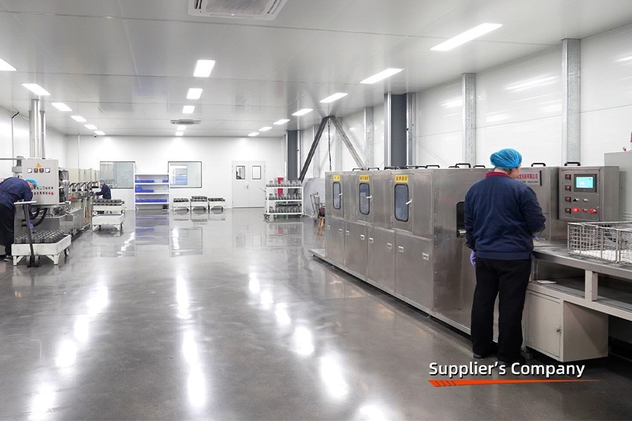
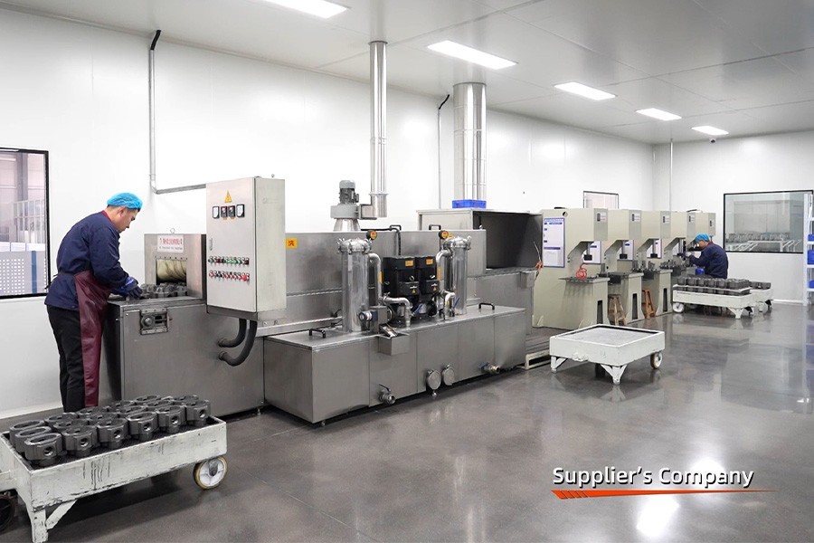
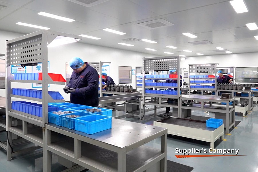
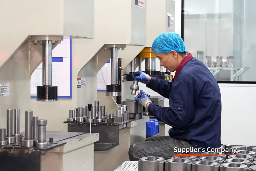
Bei Boxinhuasheng Hydraulic Technology Co., Ltd. stellen wir hydraulische Hochdruck-Zahnradpumpen und Axialkolbenpumpen her, die für anspruchsvolle mobile Anwendungen konzipiert sind. Auf unserem 68.000 m² großen Campus in Qingzhou, China, kann sich Boxinhuasheng auf über 25 Jahre Erfahrung im Ingenieurwesen, über 260 fortschrittliche CNC-Maschinen, 35 leitende Hydraulikingenieure und IATF 16949-Qualitätsverfahren verlassen, um jährlich über 1,5 Millionen Hydraulikeinheiten an OEMs in über 80 Ländern zu liefern.
Dieser technische Leitfaden beschreibt eine Schritt-für-Schritt-Methode zur Auswahl von Hydraulikpumpen für mobile Maschinenanwendungen.
Schritt 1: Berechnung der erforderlichen volumetrischen Verschiebung ($V_d$)
Die primäre Berechnung bei der Auswahl einer Hydraulikpumpe bestimmt die volumetrische Verdrängung pro Umdrehung ($V_d$, ausgedrückt in $cm^3/Umdrehung oder $in^3/Umdrehung).
┌──────────────────────────── ────────────────────────────┐
                  │ VERDRÄNGUNGSGLEICHUNGEN DER HYDRAULIKPUMPE │
                  └───────────────────────────┬ ────────────────────────────┘
                                              │
         ┌────────────────────────────── ┴──────────────────────────────┐
         ▼ ▼
┌──────────────────── ────────────────────┐ ┌──────────────────── ────────────────────┐
│ Zieldurchflussgleichung │ │ Erforderliche Verschiebungsgleichung │
├──────────────────── ────────────────────┤ ├──────────────────── ────────────────────┤
│ $Q_{req} = \sum Q_{Aktuatoren} \cdot FF$│ │ $V_d = \frac{Q_{req} \cdot 1000}{n_{Motor} \cdot i \cdot \eta_v}$│
│ Wobei $FF$ der Gleichzeitigkeitsfaktor ist │ │ Wobei $i$ das Antriebsübersetzungsverhältnis ist │
└──────────────────── ────────────────────┘ └──────────────────── ────────────────────┘
#### Beispiel für eine mathematische Größenbestimmung:
- Zielflussanforderung ($Q_{req}$): Angenommen, ein mobiles Traktorhydrauliksystem erfordert60 l/minbei einer Motorbetriebsdrehzahl von2.000 U/min.
- Antriebsübersetzungsverhältnis ($i$): 1,0 (direkter Wellenantrieb).
- Angenommener volumetrischer Wirkungsgrad ($\eta_v$): 90 % (0,90) für eine Hochdruck-Außenzahnradpumpe.
- Verschiebungsberechnung:
$$V_d = \frac{60 \cdot 1000}{2000 \cdot 1,0 \cdot 0,90} = 33,3\ cm^3/rev$$
Ein OEM-Ingenieur würde einen Standard auswählenHydraulische Zahnradpumpe mit 34 $cm^3/Umdrehungaus dem Produktkatalog von Boxinhuasheng.
Step 2: Evaluating Continuous vs. Peak Pressure Limits
Mobile Hydraulikpumpen arbeiten in unterschiedlichen Druckbereichen. Bei der Auswahl einer Pumpe müssen sowohl kontinuierliche als auch intermittierende Spitzendruckwerte anhand der Arbeitszyklen der Anwendung überprüft werden:
+-----------------------------------------------------------+
|                  Leitfaden zur Auswahl des Druckregimes |
+------------+-----------------------+----------------------+
| Maschinenarbeitszyklus | Recommended Pump Tech | Nominal Working Press|
+------------+-----------------------+----------------------+
| Leichte Landwirtschaft | Aluminum Body Gear    | 16 - 20 MPa          |
| Implementiert | Pump                  | (160 - 200 bar)      |
| Mittelschwere Lader & | Cast Iron Body Gear   | 20 - 25 MPa          |
| Muldenkipper | Pump                  | (200 - 250 bar)      |
| Schwere Bagger & | High-Pressure Axial   | 31.5 - 45 MPa        |
| Bergbaubohrer | Piston Pump           | (315 - 450 bar) |
+------------+-----------------------+----------------------+- Druckstoßpuffer: Stellen Sie sicher, dass die ausgewählte Pumpe mindestens über einen zeitweiligen Spitzendruckspielraum verfügt20–25 % über den Einstellungen des Überdruckventilsum Stoßwellen zu absorbieren, die durch plötzliche Richtungsventilverschiebungen verursacht werden.
Schritt 3: Überprüfen des Antriebsdrehmoments und der Wellenfestigkeit
Die Antriebsmaschine (Motor oder Zapfwelle) muss ausreichend mechanisches Drehmoment ($T_{input}$) bereitstellen, um die Pumpe unter maximalem Betriebsdruck ($P_{max}$) zu drehen:
$$T_{input (N\cdot m)} = \frac{V_d (cm^3/rev) \cdot P_{max} (bar)}{20 \cdot \pi \cdot \eta_m}$$
Wobei $\eta_m$ der mechanische Wirkungsgrad ist (~ 0,90 - 0,93).
Wenn das Eingangsdrehmoment die strukturelle Schergrenze der Pumpeneingangswelle (mit Passfeder, Keilnut oder konisch) überschreitet, kommt es zum Bruch der Welle. OEM-Ingenieure müssen die Auswahl des Wellenprofils an das Eingangsdrehmoment anpassen:
- Keilwellen: Geeignet für Zahnradpumpen mit geringerem Drehmoment und mittlerem Druck.
- Evolventen-Keilwellen (SAE 9T, 11T, 13T, 14T): Unverzichtbar für Zahnrad- und Kolbenpumpen mit hohem Drehmoment und hohem Druck, da die Rotationsbelastung gleichmäßig auf mehrere Zahnradverzahnungen verteilt wird.
Schritt 4: Passende Montageflansche und Anschlussstandards
Globale Hersteller mobiler Maschinen verwenden standardisierte mechanische Montageflansche, um die Drop-in-Kompatibilität sicherzustellen:
┌──────────────────────────── ────────────────────────────┐
                  │ GLOBALE STANDARDS FÜR PUMPENMONTAGEFLANSCH │
                  └───────────────────────────┬ ────────────────────────────┘
                                              │
         ┌────────────────────── ────────┬─────┴───────── ───────────────┬─────── ───────────────────────┐
         ▼ ▼ ▼ ▼
┌──────────────────┐ ┌──────────────────┐ ┌──────────────────┐ ┌──────────────────┐
│ SAE A / B / C │ │ ISO 3019 4-Loch │ │ Europäische 4-Loch │ │ Italienische Gruppe │
│ 2-Loch und 4-Loch │ │ Metrische Flansche │ │ (Eurogruppe 2/3) │ │ Flanschbefestigungen │
└──────────────────┘ └──────────────────┘ └──────────────────┘ └──────────────────┘- SAE A/B/C-Flansche: Vorherrschender Standard bei nordamerikanischen Geräteherstellern.
- Europäische Flansche der Gruppen 2 und 3: Weit verbreitet auf europäischen Plattformen für landwirtschaftliche Traktoren.
- Flüssigkeitsanschlüsse: Geflanschter Split-Port SAE J518 (Code 61 / Code 62) oder Gewindeanschlüsse (SAE ORB, BSPP) passend zu Einlass- und Auslassschläuchen.
Schritt 5: Saugbedingungen und Kavitationsverhinderung
Pumpenkavitation tritt auf, wenn der Druck in der Saugleitung unter den Öldampfdruck fällt, was dazu führt, dass mikroskopisch kleine Dampfblasen heftig gegen die Innenverzahnung oder die Kolbenschuhe kollabieren. Kavitation zerstört schnell das Innere der Pumpe.
Um Kavitation bei der Pumpenauswahl zu verhindern:
- Flüssigkeitsgeschwindigkeit in der Saugleitung: Halten Sie die Geschwindigkeit der Saugleitung niedriger1,2 m/s.
- Einlassvakuumgrenze: Stellen Sie sicher, dass das Einlassvakuum nicht überschritten wird-0,2 bar (-15 cmHg)unter Kaltölstartbedingungen.
- Verschiebungsgrenzen: Pumpen mit höherer Verdrängung (> 80 $cm^3/U) erfordern größere Sauganschlüsse oder die Montage eines überfluteten Saugbehälters.
Käufer-Checkliste: Bewertung der Qualität von Hydraulikpumpen
Bei der Beschaffung von Serien-Hydraulikpumpen für OEM-Ausrüstungsverträge sollten Einkaufsleiter Folgendes vorschreiben:
- [ ]Überprüfung der volumetrischen Effizienz: Stellen Sie sicher, dass Testzertifikate den volumetrischen Wirkungsgrad ($\eta_v > 90\%$) bei vollem Betriebsdruck und -temperatur belegen.
- [ ]100 % End-of-Line-Workload-Tests: Stellen Sie sicher, dass 100 % der hergestellten Pumpen Druck-, Durchfluss- und internen Dichtheitsprüfungen unterzogen werden (Boxinhuasheng testet 100 % auf über 30 Prüfständen).
- [ ]Automobilzertifizierung: Bestätigen Sie die IATF 16949-Qualitätszertifizierung und die Überprüfung des SGS-Werksaudits durch Dritte.
Abschluss
Die Auswahl der richtigen Hydraulikpumpe für mobile Maschinen erfordert eine systematische Analyse der Volumenverdrängung, des Dauer- und Spitzendrucks, des Eingangsdrehmoments, der Montageflansche und der Saugdynamik. Durch die genaue Anpassung der Pumpenparameter an die Arbeitszyklen der Geräte verbessern OEMs die Kraftstoffeffizienz, die Maschinengeschwindigkeit und die Langlebigkeit der Komponenten.
Boxinhuasheng Hydraulic Technology Co., Ltd. verfügt über mehr als 25 Jahre Erfahrung in der Hydraulikfertigung, 35 leitende Ingenieure, eine Jahreskapazität von 1,5 Millionen Einheiten, die Qualitätszertifizierung IATF 16949 und die SGS-Werksverifizierung, um globale Geräte-OEMs zu bedienen.
Um auf Tools zur Pumpendimensionierung zuzugreifen, 3D-CAD-Zeichnungen herunterzuladen oder Angebote für die Serienproduktion anzufordern, besuchen Siewww.chinesehydraulic.com.